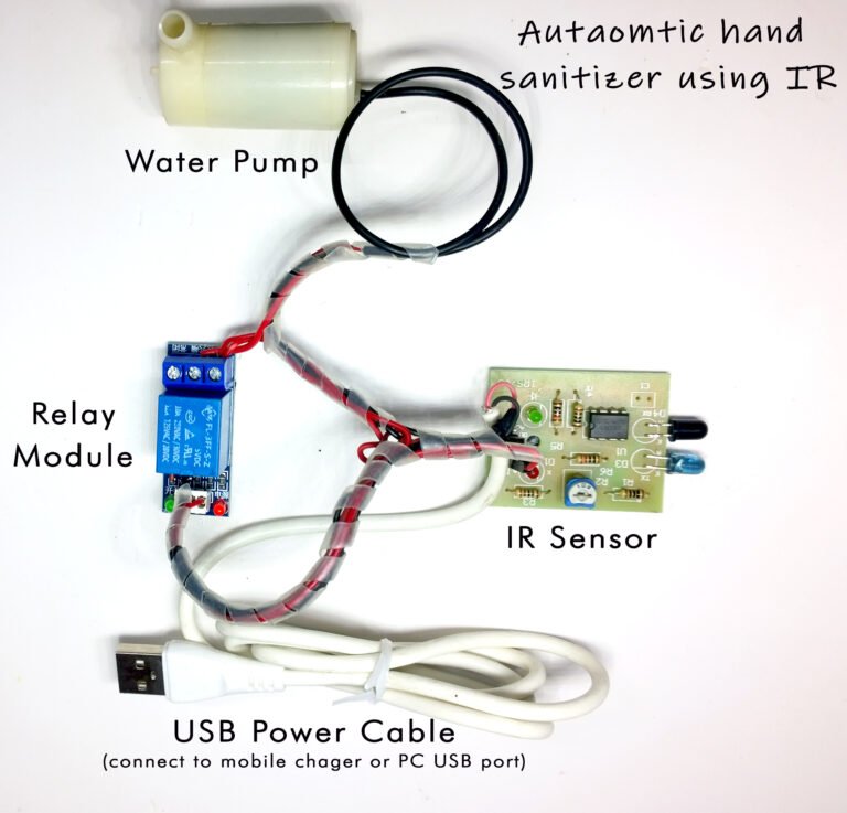
Automatic Hand Sanitizer using IR, Ready Kit, 100% Tested
Abstract
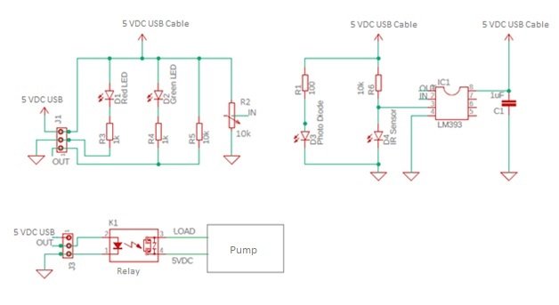
Automatic Hand Sanitizer using IR circuit is presented here is based on the readily available IR sensor, comparator IC LM393 and relay. The photo diode is used as the light intensity detector while IC LM393 used as comparator. IR beam is continuously falling on photodiode. On interruption the movement is detected. Hence, no IR beam falls on the photo diode. As a result photo diode stop conducting and water pump starts. However, when IR beam falls on the photo diode, photo diode starts conducting and water pump stays off.
Buy Online “Automatic Hand Sanitizer Using IR” Ready Kit, 100% Tested from below and get fastest delivery in India
https://smartxprokits.in/product/automatic-hand-sanitizer-using-ir-kit-assembled-100-tested/
Complete working video can be seen from
Follow us on Instagram
Application of the circuit:
Most of the IR based circuits available in market use one or another kind of IR sensor which increases the cost and also require complicated circuitry around it. But this IR based circuit uses readily available IR sensor as IR beam detector. The functioning of this Automatic Hand Sanitizer using IR is to detect interruption in IR beam falling on photo diode and automatically activate the pump in absence of beam. Water pump continuously indicating the absence of beam till beam falls on the photo diode.
Why this particular circuit:
IR sensor used here as a beam detector. The variation in beam wanted can be easily done by interrupting IR beam using hand palm. The circuit operates normally over a DC voltage of 5V which can be obtained by DC supply cable.
Explained working of circuit:
The basic idea behind the circuit operation is to turn ON pump in absence of IR beam. The photo diode is needed for this purpose. Photo diode is photoelectric device as it converts light energy to electric energy. Here, Automatic Hand Sanitizer using IR works as IR beam detector while photo diode working as light sensor that pumps water. IC LM393 is used as comparator. Photo diode output is connected as input to comparator. Pin no. 4 of LM393 is pulled towards ground. Relay is used as a switch. When relay is activated, normally closed contact becomes open and normally open contact becomes closed. In normal condition, IR beam falls on photo diode and water pump stays off. Now consider second scenario when IR beam is irrupted, the water pumps in the absence of light.
How to build:
First of all read the given manual thoroughly and study the circuit given in the figure. Also have look at PCB and components supplied along with the kit. Each component has to be soldered in its position on PCB.
Identification of resistors is done by color coding. The color band on each resistor corresponds to its exact value.
There are different methods in which values are defined on capacitors. But usually values are specified numerically on them.
Can you make out the whole working of circuit and are you able to identify each component separately as to where each of them has to be placed?
If yes only then proceed further to actually mounting and soldering the parts.
Not ICs but their sockets are to be soldered on PCB. This is to make mounting and dismounting of ICs easy while troubleshooting.
Start from left most corner of PCB and solder the components one by one on their correct position on PCB.
Before soldering any component see that you have placed it at its right position and with correct polarity. Give due attention to diodes and electrolytic capacitors as they are polarity dependent.
Do the soldering of other components in the same way while keeping in mind that components with long and sensitive leads like capacitors and transistors are soldered last.
Testing the kit:
After assembling and soldering of components on PCB, connect external DC power source of 5V.
For testing purpose manually hold hand palm over IR sensor. Water pumps in this case.
Now set the desired intensity at which you want detection of light. This can be done by changing the resistive value of R2 variable resistor.
Install the unit in room.
ICs used here:
The only IC used here is LM393
It is dual differential comparator IC.
This 8 pin IC is popular and commonly used IC
Part List
Semiconductors
U1 – LM393
https://smartxprokits.in/product/lm393/
Base – 8 pin
https://smartxprokits.in/product/8-pin-dip-ic-socket-base-adaptor/
Resistors(all ¼ watt +/-5% carbon unless stated otherwise)
R1 – 100 Ohm
https://smartxprokits.in/product/100-ohm-resistor-1-4-watt/
R2 – 10k Ohm(variable)
https://smartxprokits.in/product/10k-multiturn-potentiometer/
R3 – 1k Ohm
https://smartxprokits.in/product/1k-resistor-1-4-watt/
R4 – 1k Ohm
https://smartxprokits.in/product/1k-resistor-1-4-watt/
R5 – 10k Ohm
https://smartxprokits.in/product/10k-resistor-1-4-watt/
R6 – 10k Ohm
https://smartxprokits.in/product/10k-resistor-1-4-watt/
Capacitor C1 – 1uF
Miscellaneous
D4: – IR Sensor
https://smartxprokits.in/product/5mm-ir-led-infrared-led/
D3: – Photo diode
https://smartxprokits.in/product/photodiode/
D1: – Red LED
https://smartxprokits.in/product/3mm-red-led/
D2: – Green LED
https://smartxprokits.in/product/3mm-green-led/
5 V USB Cable
https://smartxprokits.in/product/micro-usb-cable/
PCB
Pump
https://smartxprokits.in/product/5v-dc-mini-submersible-water-pump/
Relay
https://smartxprokits.in/product/5v-10a-pcb-mount-relay-spdt/